Game Boy Zero
The Game Boy Zero is a custom portable game machine that is capable of storing and playing thousands of games ranging from Atari 2600 to Sony Playstation. It's made from an original Nintendo Game Boy enclosure and a Raspberry Pi Zero computer. It's powered by a rechargeable lithium-polymer battery. It includes built-in audio, video, controls, optional HDMI video output, and a USB port for additional controllers.
My good friend commissioned me to build this for him. It was a great opportunity to learn about different video and audio solutions, like I2S (Inter-IC Sound Bus) digital audio, and implementing RetroGame a utility for mapping GPIO (General Purpose Input/Output) signals to a USB input device.
Wermy from Sudomod did a similar project and I got a lot of ideas and information from his blog.
One very key difference between Wermy's Game Boy and mine is that he used an all-in-one board that included: a USB hub for button inputs, pulse-width modulation (PWM) filter, audio amplifier, and analog stick input. I would have liked to use the same all-in-one board, but I wasn't able to get one at the time. Besides, doing it differently was more educational for me. I wanted to use general-purpose parts to make my Game Boy Zero and learn more about some different technologies.
Another difference is that Wermy made some 3D printed parts and offered them for sale in his store, but I made some 3D printed parts and I'm offering them for free on Thingiverse (link).
Lastly, Wermy made a custom Game Boy cartridge that had an SD card in it to store the OS and games. It was a neat aesthetic, but I decided not to do that. A cartridge does make it easier to remove the SD card, but it would have been a lot of work and my friend didn't necessarily want it.
Contents
- 1 Video
- 2 File Downloads
- 3 Hardware
- 4 Software
- 5 Lessons Learned
- 6 Links
|
Key Features:
|
Components:
|
Update: I've since found a nice kit with a case, button PCB, speaker, and other plasticware (source).
Video
File Downloads
| Filename | Description | Size | Modified | Link |
|---|---|---|---|---|
|
RetroBoy_FINAL_1.0.img.gz |
SD Card image of my completed Retropie install. 4GB uncompressed; can expand to any size. |
777M | 4/3/2018 | |
|
Game_Boy_DMG-01_Button_Well_and_Screw_Bracket.zip |
3D print files (STL). | 274K | 4/3/2018 | |
|
RetroGame.zip |
Install script for controller drivers. | 2.7K | 4/3/2018 | |
|
RetroBoy_Configs.zip |
Example config files. | 14M | 4/3/2018 | |
|
Scripts.zip |
Miscellaneous scripts. | 411K | 4/3/2018 | |
|
checksum.md5 |
Checksums for all files (md5). | 293B | 4/3/2018 | |
|
checksum.sha512 |
Checksums for all files (SHA512). | 773B | 4/3/2018 |
Hardware
Game Boy Enclosure (DMG-01)
Removing Material
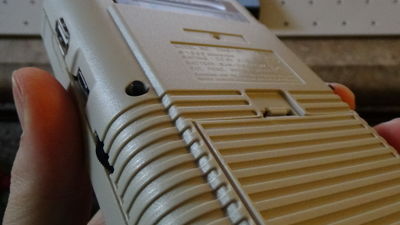
To make room for all the additional components I had to remove a lot of material from the case, especially the battery compartment. This is by far the most frustrating part of the project, so work slowly and measure often.
It's important to remove material incrementally and only remove what you need! In other words, when you've chosen a place to put something, grind away enough to just fit that component. As you progress and add new components, grind away more as needed.
Don't remove critical structure unless you need to! Use a marker to mark the screw holes and find a way to work around them.
I used a Dremel to remove most of the material where appearance is not important, and I used an X-Acto knife to make more precise cuts. I was pretty satisfied with the cut around the screen. I used a caliper to define the width of the edge, running it along the inner edge of the recession leaving a scratch mark outlining exactly where I wanted to cut. An X-Acto knife, some small fine-tooth files (both round and triangular), and sand paper were my weapons of choice. Oh, and lots of patience.
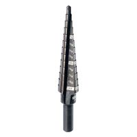
The button holes were easily positioned using the paper template provided with my button PCB (if the seller's listing doesn't mention providing a template, ask them if it comes with one). I marked the drill points with an awl and used a step drill bit to cut the holes, which is nice for two reasons: 1) it starts with a small bit and makes it easier to start the hole, and 2) each step chamfers the edge for the previous step. I drilled from the outside of the case because it gives it a cleaner edge.
The template said to drill it to 7/16 inch, but you should always err on the safe side and drill it smaller, see how the button fits, then drill more as needed.
Another thing I had to do was cut a new slot for the volume knob, as the original slot is being used for HDMI. I first outlined the area I wanted to cut with blue painter's tape. I then used a "scooping" technique with an X-Acto knife to get reasonable precision. I've drawn a crude graphic illustrating my technique.
3D Printed Parts
Unfortunately, I had to remove some of the screw posts to make room for the screen. I made a 3D printed bracket that provides screw holes behind the screen. I also created several stand-offs and mounting brackets for various things, but they are not critical to the structural integrity of the case. If you don't have a 3D printer, you can order similar parts from Sudomod here and here. Otherwise, you can download my files for free from Thingiverse (link).
The button wells are also important to keep the buttons in place. After gluing them in, put the buttons in and test them out. If it doesn't feel quite right, wrap some fine-grit sand paper around a screwdriver (or something round) and sand down any edges that are catching on the buttons.
I also printed various small blocks and used scrap 3D print pieces to act as spacers. I didn't include these because anyone can use scrap material to fill gaps and what not.
I printed everything in ABS, 100% infill, a raft, and no supports. In case you want to know, my printer is a CTC Bizer (the first model). I bought it when it was $300, and I've modified it so heavily that it's pretty much an entirely different printer. I get very decent prints for a total cost of no more than $400 (yes, I'm bragging).
Buttons
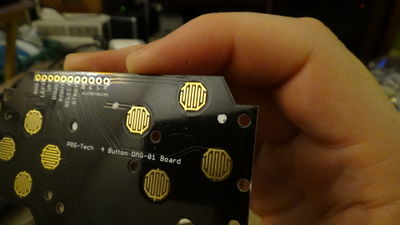
The button PCB that I bought is simply an arrangement of contacts for silicone keypad switches that act as the control inputs. There are no actual components on this board, only button contacts and a row of through-hole solder points.
Custom Ordered Parts
I ordered some cosmetic parts from http://www.retrofresh.uk/ and they really make the project complete! The screen cover was essential to hide the rough-cut screen bezel and give it an original Game Boy look. I also bought a couple of cartridge labels with some beautiful original art (many are more intricate than the one pictured below). The aftermarket cartridge I bought was just an eBay buy. I love how it just says GAME!
|
|
Structural Integrity
Just an extra note about structure: imagine the device being dropped and try to imagine the weak points. I tend to apply glue very liberally and I put kapton tape wherever I see potential for electrical shorts (other kinds of tape will do). I may also add strips of foam, popsicle sticks, 3D printed parts, and more. Sometimes it's prudent to screw things down in addition to gluing them (the ol' screw-n-glue). Time is very costly to me, so time spent servicing devices repeatedly is better spent reinforcing them once.
Raspberry Pi Zero
The Raspberry Pi Zero 1.3 is pretty self explanatory. I decided not to use the Zero W version because my friend wasn't going to use the built-in Wi-Fi and battery life was already severely limited. I added a small heat sink to the CPU for good measure. There isn't much else to say about it, so here are some reference materials.
Some technical specs and other info: https://www.raspberrypi.org/documentation/hardware/raspberrypi/README.md


Note: Throughout this page, when I reference a GPIO pin, I'm referring to the NAME, not the Pin#. For example, the second pin down on the left I will refer to as GPIO02, not pin 03. I may say "GPIO pin 2" to mean GPIO02.
SD Card
During installation and testing I used a 4GB Sandisk micro SD card. This makes it faster and easier to make daily backup images. In the final product I installed and expanded the image onto a 128GB Sandisk Extreme PRO. The Extreme PRO version is more expensive, but I wanted to use an SD card with wear leveling. This was important because the OS is installed on the Ext4 file system. Ext4 is a journaling file system, which is a "file system that keeps track of changes not yet committed to the file system's main part by recording the intentions of such changes in a data structure known as a journal" [1].
Why is this a problem for an SD card? It generally increases the number of writes to disk and will wear out the SD card faster. This really sucks for the Raspberry Pi because the OS is meant to be installed on an SD card, and almost all Pi-based Linux distros come on Ext4.
Why do Raspberry Pi OS images come on Ext4 file systems?
Probably because a journaling file system is better able to handle an abrupt system halt, like unplugging the system. Raspberry Pi's are often used for applications that require that kind of flexibility. The thing doesn't even have a power button.
What is wear leveling?
"A technique for prolonging the service life of some kinds of erasable computer storage media." [2]
So what are my options?
- Use an SD card that has wear leveling such as a SanDisk Extreme PRO (not SanDisk Ultra).
- If you have a choice, use a non-journaling file system, such as Ext2.
- If your application calls for heavy disk writing, consider writing data to a hard drive or SSD.
All things considered, I chose option 1. I don't expect extremely heavy disk writing, but later on in my project I do reconfigure RetroArch to write to the memory card for Playstation emulators at 2 second intervals to alleviate another problem (see Playstation Saving).
Display
Disassembly
The BW 3.5 Inch TFT LCD Monitor is a cheap product, so before you disassemble it, give it a test run to look for dead pixels or any other problems. If you have some extra cash, I would recommend buying two of them in case one of them is crap. Why not buy a more expensive one instead of two cheap ones? Even expensive ones can arrive broken. Buying two can give you some flexibility. The second one can be a backup in case you break the first one, and if they both end up working fine you now have another screen that you can use for another project.
The display is a bit difficult to disassemble. After unscrewing the backside, you still have a screen cover that is stuck on with adhesive. Sometimes using a heat gun is a good way to loosen up adhesives, but in this case I didn't want to cause any warping of the screen itself, so I very carefully separated the cover by cutting around the edges with an X-Acto knife. I made sure to cut all the way around the screen, lifting as much as I could with the knife before pulling it off by hand.
Once I had freed the screen from its bezel, I cleaned off the adhesive with Zippo lighter fluid (or Ronsonol). You could also use Goo Gone.
Setup
The screen is attached to a display driver through a ribbon cable. The display driver then has four input wires:
|
I don't remember what the white wire is for, but I didn't use it. In addition, there is a 3 button PCB attached using a small white connector (left side). These are display adjustments, such as brightness and contrast. I never needed to use them, but I included them in the final product anyway. They were long post-style tactile buttons, and I cut them shorter to make them fit in the crowded interior of the Game Boy Zero.
Brightness, contrast, and hue controls for the display.
Wiring diagram for display:

Note: The 5V and GND go directly to the Powerboost, not the Raspberry Pi.
Power Modification
The display driver requires about 5.5V to 6V to run, but we can only provide 5V, so we need to make a modification suggested by Wermy. Take a small insulated wire and solder it between the 5V IN (red wire) and pin 2 of the the 8-pin IC (which I believe is a DC-to-DC step-down converter). The chip has a notch indicating pin 1, so pin 2 is the next pin down (on the same side).
For software configurations, go to Display Config.
Audio
Audio Module
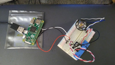
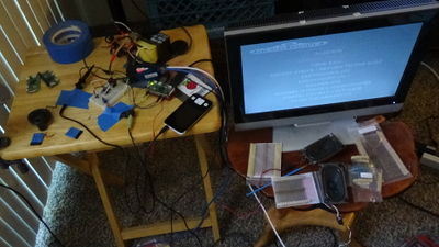
I had a lot of trouble finding the best audio solution for this project. At first I tried pulse width modulation (PWM) by re-assigning the GPIO pins on the Raspberry Pi to generate two channels of PWM output then using a low-pass filter to get the audio signal. I used a software utility suite called WiringPi, but I never got it to work with Emulationstation. It seemed to cause Alsa to crash. There are a few good tutorials out there describing how to set up WiringPi on a fresh Raspbian install (which worked fine when I tried it), but my efforts to resolve the compatibility issues with Emulationstation began to outweigh the benefit. I then tried Pigpio, but it was much the same story. I was done with PWM. Besides, it is supposedly not the best quality audio you can get from a Raspberry Pi.
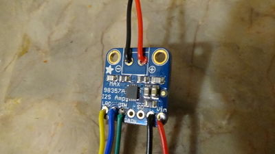
After rethinking my approach, I decided to go with an entirely different technology: I2S (Inter-IC Sound Bus), which is a serial audio protocol. I purchased the Adafruit I2S 3W Class D Amplifier MAX98357A (source), which has a Digital-to-Analog Converter (DAC) with an amplifier built in. It produces high quality audio and it can be very energy efficient in low watt modes. For clarification, I2S does use PWM, but it's not the same as using just PWM (source). I wired it as follows:
| I2S Module Input | GPIO Pin | Powerboost 500C | 8 Ohm Speaker | Wire Color |
|---|---|---|---|---|
| LRC | GPIO 19 | yellow | ||
| BCLK | GPIO 18 | blue | ||
| DIN | GPIO 21 | green | ||
| Vin | 5V+ | red | ||
| GND | GND | black | ||
| Out (+) | (either pin) | red | ||
| Out (-) | (either pin) | black |
It's important that this module doesn't require a Master Clock (MCLK) input, as there are apparently no DAC drivers for Raspberry Pi Zero that support it (indicating that the hardware simply doesn't support it).
Notice that I powered it directly from the Adafruit Powerboost 500C instead of through the Pi. I did this because I decided to run it on 5V and there was no other reason to power it through the Pi. If I wanted to save overall power and run the I2S module on 3.3V, I would have drawn the power from the Pi, but that might put the Pi at risk of having insufficient power to run some CPU-intensive games and audio at the same time. I didn't test this, I just went with that reasoning.
I tried out the gain setting on the I2S module, but I was satisfied with the default gain level. If you want to change it, wire a resistor as follows:
- 15dB if a 100K resistor is connected between GAIN and GND
- 12dB if GAIN is connected directly to GND
- 9dB if GAIN is not connected to anything (this is the default)
- 6dB if GAIN is conneted directly to Vin
- 3dB if a 100K resistor is connected between GAIN and Vin
Wiring diagram for audio:

Note: The 5V and GND go directly to the Powerboost, not the Raspberry Pi.
What if I wanted stereo? This module is for a single audio channel. If you want stereo sound, you will either need two modules, a different module that supports stereo, or you could set up something clever with the left/right channel select and rapidly switch back and forth between channels (I'm speculating). For my application, mono was sufficient and I wanted to minimize power consumption.
Another good tutorial: https://learn.adafruit.com/adafruit-max98357-i2s-class-d-mono-amp
Other Audio Hardware
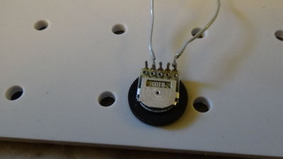
The audio system also includes a 3.5mm audio socket, an 8 ohm speaker (28.5mm diameter), and a B103 10k ohm wheel potentiometer. The audio socket has a switch that allows it to change audio channel when a jack is inserted. I used this to disable the speaker when headphones are being used. The left and right channels on the audio socket are bridged to make it mono. Also, the speaker and the potentiometer don't care which wire is which. In other words, as long as you follow my diagram the two wires can be switched and the result will be the same. Be sure that the speaker is rated for the wattage that is put out by the DAC/amp. My configuration demands that the speaker handle at least 1.4W. The potentiometer was wired so that the resistance increases as the wheel is turned clockwise (with the "B103" label facing you).

Note: Some of these pictures show different speakers, but they all have the same specs.
For software configurations, go to I2S Audio Config.
Controls
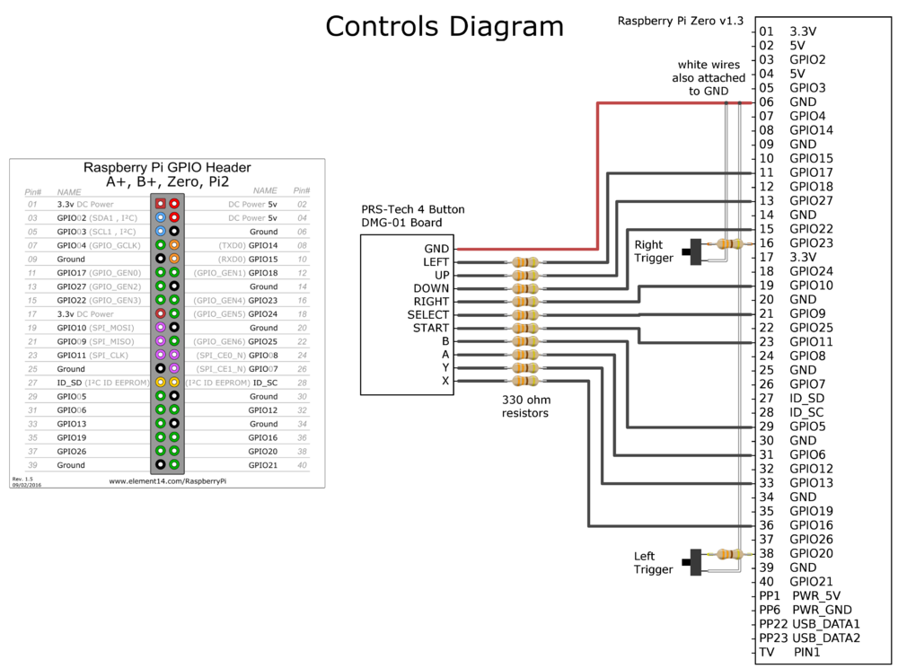
The controls are very simple: each button on the control PCB maps to a single GPIO pin on the Raspberry Pi. They all share a common ground. I added two tactile buttons for the left and right triggers that also map to GPIO pins.
For very basic (lazy) protection of the GPIO pins, I added 330ohm resistors to each of the button inputs. This means that the path of least resistance will usually be through the ground pin, but this really doesn't protect against most over-volt situations. If you want proper protection, look into Zener Clamping. I don't seem to have any floating pin problems, so I don't think I needs any pull down resistors (even though I really should use them). Also, the rubber buttons don't have much bounce, so I don't need to worry too much about repeated inputs. The message here is: I'm lazy.
Control-to-GPIO mapping:
| |||||||||||||||||||||||||||||||||||
| Note: I changed the pinout since I took the photos above. The tables to the left are correct. | |||||||||||||||||||||||||||||||||||
Wiring diagram for the controls:
USB Port:
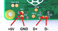
To setup the USB port I simply re-routed the USB data pins on the Raspberry Pi to a type-A USB port. It's important to twist the two data wires as tightly as possible. If you don't, the wires might cause interference (called "crosstalk") and the signal will be poor. The 5V and GND power pins go the the PowerBoost module, not the Raspberry Pi. See the Power Section for more info.
Wiring diagram for USB:
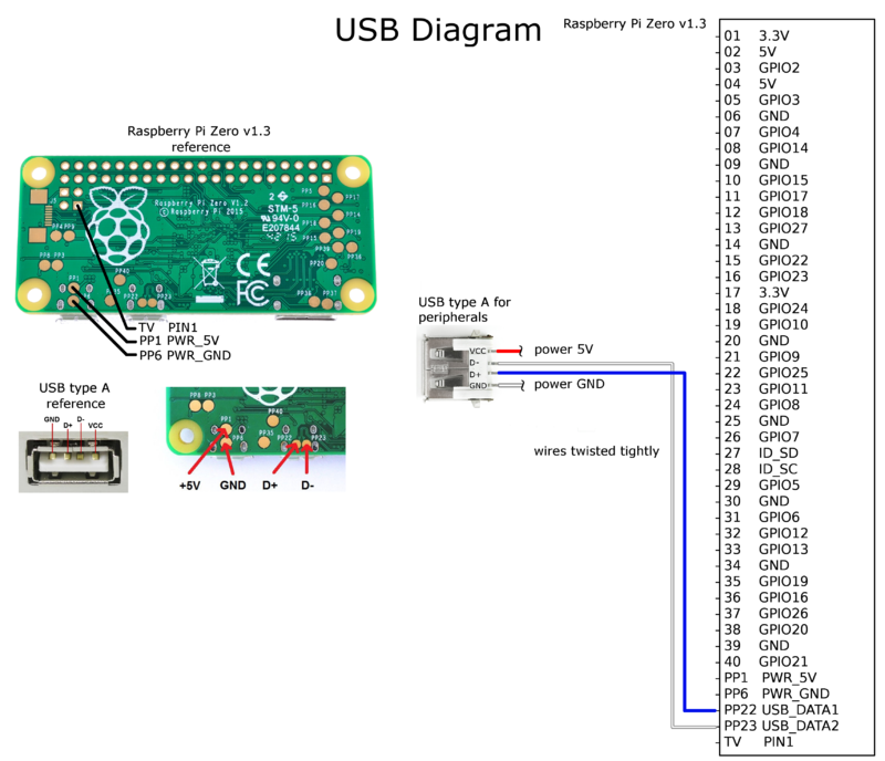
Note: The 5V and GND go directly to the Powerboost, not the Raspberry Pi.
A tip for USB adapters:
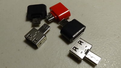
One of the best things I did for testing on the Raspberry Pi Zero is buy these cheap little USB to micro USB adapters. The USB ports on the Raspberry Pi Zero are really close together, so finding adapters that can plug in adjacent to another device is difficult (or more expensive). These things are super cheap; I got these for $0.30 a piece on aliexpress.com. All you have to do is cut the colored plastic shell off of them with some wire snips. Try searching "mini otg usb to micro usb adapter".
Power
Everything in the Game Boy Zero is powered by a 3.7v 2500mAh LiPo battery (51mm x 65mm x 8mm). Power distribution and charging are controlled by the Adafruit Powerboost 500C. It provides 5.2V of power to all of the components, and it can charge on any 5V micro USB charger. It can handle up to 1A of current.
Unfortunately, I discovered the Powerboost 500C can't run and charge the battery at the same time. Even if you have it plugged into a 5V power source the battery will still drain and eventually die. So you do have to turn it off every once in a while to charge. I read that this will happen when you draw more than 500mA, but I don't think the Game Boy Zero is drawing that much so I'm not sure what's happening. Next time I will go with the Adafruit Powerboost 1000C which has load-sharing.
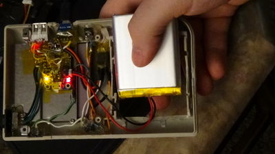
You can see that I also re-routed the low-battery LED to a red LED near the USB ports. This is just to make it more visible when the case is fully assembled. Note that there is a pin labelled "LB" for low-battery but it is actually turned on when the battery is NOT low. That's not what I want. I could have set up a small circuit to create the proper behavior, but why? There is already an LED that does what I want.
Also, a note about spacing: notice that I have PCBs on each of the two shells of the casing that, when assembled, will be sandwiched together. It's very important to ensure that nothing is touching. They actually fit together nicely in this case, but I still covered the Powerboost in kapton tape when I was done. Hot glue can hold pretty well, but I always imagine what might happen if this thing was dropped. I would much rather my friend tell me "something is loose inside" instead of "something is loose inside and it won't turn on."

Note: I added a wire extension for the battery to make it possible to unplug the battery without disassembling the case.
I want to address the gray ribbon cable with the two white connectors in the second photo above, because it may cause some confusion. This cable passes power and data between the two shells of the case. The small connector on the left is power. It seemed a bit flimsy with only two wires so I doubled up the wires. That's why you see four wires coming out of it, even though it's only a 2-pin connector. The wide connector on the right also has four wires and it is for control inputs. It has left trigger, right trigger, the "safe power off" button, and ground. See the Controls Section for more info on that.
Wiring diagram for power distribution:
For power configurations, go to Power Config.
Software
RetroPie
RetroPie is a suite of software that brings together different gaming platforms into one clean, organized game library and menu system. It also lets you centrally manage configurations across different emulators. I used the pre-made Raspbian image. In my Game Boy Zero project, I installed version 4.1.
This version of RetroPie comes with emulators for the following platforms:
|
|
|
See all supported systems as of RetroPie version 4.3 here.
RetroPie is a combination of:
| Raspbian | A Linux distribution that is a port of Debian for the Raspberry Pi. This is my preferred operating system for this project, but there are others available for running RetroPie. |
| Emulationstation | Graphical interface for managing your game library. It lets you easily configuring controllers, audio, and more. |
| RetroArch | Unified frontend for emulators that lets you manage audio, video, control, and other configurations across all your emulators. It uses the Libretro API. In RetroPie, RetroArch is integrated with Emulationstation. |
Much of this information can be easily found on other sites, but since I refer to these different things in this page, I figured I should briefly explain the differences.
Display Config
These are the software configurations for all things related to display. For display hardware setup click here.
Screen Resolution
I changed the screen resolution to that of the display device, which is 640x480. You can change this in the /opt/retropie/config/all/retroarch.cfg file. The important values are:
video_fullscreen_x = "640"
video_fullscreen_y = "480"
Contents of my /opt/retropie/config/all/retroarch.cfg file. I've removed all commented lines here. In other words, make sure the file has only these lines uncommented (if you are setting it up exactly like mine):
cache_directory = "/tmp/retroarch"
core_options_path = "/opt/retropie/configs/all/retroarch-core-options.cfg"
system_directory = "/home/pi/RetroPie/BIOS"
config_save_on_exit = "false"

video_fullscreen_x = "640"
video_fullscreen_y = "480"

video_threaded = "true"
video_smooth = "false"
video_aspect_ratio_auto = "true"
video_font_size = "12"

input_joypad_driver = "udev"
input_autodetect_enable = "true"

input_player1_a = "z"
input_player1_b = "x"
input_player1_y = "s"
input_player1_x = "a"
input_player1_start = "enter"
input_player1_select = "ctrl"
input_player1_l = "w"
input_player1_r = "q"
input_player1_left = "left"
input_player1_right = "right"
input_player1_up = "up"
input_player1_down = "down"
input_player1_l2 = "e"
input_player1_r2 = "r"

input_state_slot_increase = "right"
input_state_slot_decrease = "left"
input_exit_emulator = "enter"
input_shader_next = "m"
input_shader_prev = "n"
input_rewind = "r"
input_reset = "x"
input_menu_toggle = "a"

all_users_control_menu = "true"
menu_driver = "rgui"

rewind_enable = "false"
rewind_buffer_size = "10"
rewind_granularity = "2"

video_gpu_screenshot = "true"

input_enable_hotkey = "ctrl"
auto_remaps_enable = "true"
Font Size
The default font size in Emulationstation was a bit too small for the tiny screen, so I increased it.
Edit the file /etc/emulationstation/themes/carbon/carbon.xml and look for a section that starts with the tag <textlist name="gamelist">. It should look like this (although it looks slightly different in updated versions):
<textlist name="gamelist">
		<selectorColor>1c1c1c</selectorColor>
		<selectedColor>8b0000</selectedColor>
		<primaryColor>969696</primaryColor>
		<secondaryColor>7a6161</secondaryColor>
		<fontPath>./art/Cabin-Bold.ttf</fontPath>
		<forceUppercase>1</forceUppercase>
		<scrollSound>./art/select.wav</scrollSound>
	</textlist>

</view>

<view name="basic">
	<textlist name="gamelist">
		<fontSize>0.0380</fontSize>
	</textlist>
</view>

<view name="detailed">
	<textlist name="gamelist">
		<fontSize>0.03</fontSize>
	</textlist>
</view>
You can see, in this case, there are two smaller sections within <view name="basic"> and <view name="detailed">. Edit one of the fontSize tags to a value that better suits your display (the fontSize tag may also be in the larger section). For my 640x480 display, I found that 0.06 was ideal.
RetroGame (Controller Driver)
RetroGame is a Raspberry Pi GPIO-to-virtual-keyboard utility for classic game emulators. It's very simple: it maps GPIO pins to keyboard keys. When you configure your controller, it will act like a keyboard, but you don't need to think about that. After installing and configuring RetroGame, you can just go into Emulationstation and configure the controller as you usually do. For controller hardware setup click here.
Installing RetroGame
To install RetroGame I followed these instructions, but I will repeat them here.
Download the RetroGame script:
curl -O https://raw.githubusercontent.com/adafruit/Raspberry-Pi-Installer-Scripts/master/retrogame.sh
If you don't trust it, read the script first to see what it does. Now run it:
sudo bash retrogame.sh
Note: In case the link no longer exists, I've provided the script in my Downloads Section.
You will get a prompt asking to select from a set of preset configurations. I chose #3 PiGRRL Zero, but it doesn't matter what you choose. These are just presets. It will then prompt you to continue. Type "y" for yes. After it installs, it will ask you to reboot the system. Type "y" to continue. Once it finishes rebooting you can edit the RetroGame config.
RetroGame Configuration
Contents of my /boot/retrogame.cfg file. I've removed most commented lines here. In other words, make sure the file has only these lines uncommented (if you are setting it up exactly like mine):
#keyboard key  GPIO
#============  ====
LEFT           17  # Joypad left
RIGHT          10  # Joypad right
DOWN           22  # Joypad down
UP             27  # Joypad up
Z               6  # 'A' button
X               5  # 'B' button
A              16  # 'X' button
S              13  # 'Y' button
Q              26  # Left shoulder button
W              20  # Right shoulder button
LEFTCTRL        9  # 'Select' button; PiTFT Button 2
ENTER          11  # 'Start' button; PiTFT Button 3
Reboot after making changes.
I2S Audio Config
These are the software configurations for all things related to audio. For audio hardware setup click here.
DTOverlay Configuration
Device Tree Overlay (DTOverlay) is a system that many Pi-based operating systems use to load modules for devices. The drivers are already on the system, you just have to enable them. You can find all the overlays in /boot/overlays (which also contains a README file). For more information on DTOverlay read this.
Contents of my /boot/config.txt file. I've removed all commented lines here. In other words, make sure the file has only these lines uncommented (if you are setting it up exactly like mine):
dtparam=i2s=on

gpu_mem_256=128
gpu_mem_512=256
gpu_mem_1024=256
overscan_scale=1

dtoverlay=rpi-dac
dtoverlay=i2s-mmap
Reboot after making changes.
Alsa Configuration
Advanced Linux Sound Architecture (ALSA) provides audio functionality. The configurations below may not be entirely necessary, but this is ultimately how I left it.
Contents of my /etc/asound.conf file:
pcm.!default {
    type            plug
    slave.pcm       "softvol"   #make use of softvol
}

pcm.softvol {
    type            softvol
    slave {
        pcm         "dmix"      #redirect the output to dmix
    }
    control {
        name        "PCM"       #override the PCM slider to set the softvol
        card        0
    }
    min_dB -5.0
    max_dB 10.0
    resolution 6
}
The min_dB, max_dB, and resolution were some things I was playing around with. You can omit them or adjust them.
You can get a list of playback hardware devices in Alsa:
aplay -l
You will see output that looks like this:
**** List of PLAYBACK Hardware Devices ****
card 0: sndrpirpidac [snd_rpi_rpi_dac], device 0: RPi-DAC HiFi pcm1794a-hifi-0 []
  Subdevices: 0/1
  Subdevice #0: subdevice #0
Notice that I only have one card, which is card 0, device 0. My /etc/asound.conf file refers to card 0.
You can test the device by playing a sound file:
aplay -D hw:0,0 sound.wav
The -D option specifies the audio device, in the form hw:X,Y where X is the card # and Y is the device #.
You can also use a tool called speaker-test but I won't get into details. Read more.
Adjust volume levels:
alsamixer
Power Config
These are the software configurations for all things related to power. For power hardware setup click here.
Manual Power Button
I wrote a short and simple Python script for shutting the system down safely using a GPIO button press. It also allows you to specify a duration that the button must be held. It wasn't entirely necessary for this project, but it's a nice touch and I've been meaning to write something like this to be used in later projects.
Here is the code:
#!/bin/python
#
# Script to shutdown Raspberry Pi when GPIO input is held.
# Connect a button between ground (GND) and the GPIO pin
# that you specify below.
#
# If you run this script from your /etc/rc.local file, it
# will be running as root, which eliminates the need to
# enter a password to elevate privileges. Otherwise, the
# sudo command will ask for a password before it will
# execute shutdown.

import RPi.GPIO as GPIO
import sys,os,signal,time

# GPIO pin number
btn = 4

# Button must be held for this many seconds
delay = 3.0

def sense_input(btn,delay):

  try:
    # Wait for button press
    GPIO.wait_for_edge(btn, GPIO.FALLING)

    count = 0
    while True:
      if GPIO.input(btn) == False:
        if count < delay:
          count = count + 1
          time.sleep(0.1)
          continue
        else:
         # Shutdown system
         os.system("sudo shutdown -h now")
         os._exit(-1)
      else:
          try:
            GPIO.cleanup()
          except:
            pass
          time.sleep(0.1)
          break

  except KeyboardInterrupt:
    try:
      GPIO.cleanup()
    except:
      pass
    os._exit(-1)

  except:
    pass

delay = delay*10
while True:
  GPIO.setmode(GPIO.BCM)
  GPIO.setup(btn, GPIO.IN, pull_up_down=GPIO.PUD_UP)
  sense_input(btn,delay)
Assuming you save this to /off-button.py go ahead and make it executable:
chmod a+x /off-button.py
Then add it to /etc/rc.local so it runs on startup. Enter the command above the exit 0 line so that it looks like this:
# ... existing rc.local stuff ...

python /off-button.py &
exit 0
Power Saving
Disable Wi-Fi: If you are using the Raspberry Pi Zero W and you don't plan to use the Wi-Fi, disable it so that it doesn't consume power.
To disable Wi-Fi, add this line to your /boot/config.txt file and reboot:
dtoverlay=pi3-disable-wifi
Disable Bluetooth: If you are using the Raspberry Pi Zero W disabling bluetooth will also help to save power.
To disable bluetooth, add this line to your /boot/config.txt file and reboot:
dtoverlay=pi3-disable-bt
Disable HDMI: Even when you're not using HDMI, the interface is enabled and consuming a small amount of power. If you don't plan to use HDMI, you can disable it.
To disable HDMI on startup, edit your /etc/rc.local file and add this line somewhere above the exit 0 line:
# ... existing rc.local stuff ...

/usr/bin/tvservice -o
exit 0
At any time, you can run this command to enable HDMI again:
/usr/bin/tvservice -p
Disable LEDs: LEDs only consume a tiny amount of power, but if you want to be really diligent with power saving you may want to consider disabling them.
To disable LEDs on the Raspberry Pi Zero, add these lines to your /boot/config.txt file and reboot:
dtparam=act_led_trigger=none
dtparam=act_led_activelow=on
Note: Disabling the LEDs on the Raspberry Pi Zero is different than on the other Raspberry Pi models. Read more about it here.
Configuration Improvements
Note: Some of these are no longer needed with newer versions of RetroPie.
Playstation Saving
Despite saving your game using the in-game save menu, you might find that your game wasn't saved because Retroarch saves the memory card data to the .srm file at certain time intervals. It's possible to turn your game off before it has a chance to truly save it. Learn how to fix this: Auto_Saving_to_Memory_Card
Game Lists in Emulationstation
For improvements in the listing of game files in Emulationstation (may not be relevant in newer versions of RetroPie): ROM_Files
Font Size in Emulationstation
For better visibility on smaller screens: Appearance
Faster Booting
Because the system doesn't need to wait for DHCP: Faster_Boot_Time
Keybindings
To change or remove RetroArch keybindings: Change/Remove_Keybindings
Optimizing for Performance
Because performance: Optimization
Lessons Learned
Modularity
I have this habit of making everything "pluggable" and socketed so that it can be removed. This often over-complicates the build and takes up more space. I sometimes do this to my detriment. My main concern is repeatedly soldering and de-soldering from a valuable component, like the Raspberry Pi, and damaging the contacts. Maybe in the future I will consider using perfboard, or something else that I don't mind damaging, and just soldering to that instead. The device probably won't need enough servicing to justify using connectors.
Functionality
I really wish I had done more research on the Powerboost 500C. When I discovered that I couldn't power the device and charge the device simultaneously, I realized I should have gone with the Powerboost 1000C. I did start my project with a list of functional requirements, but this one slipped my mind. The truth is, I didn't know the implication of load-sharing, nor did I notice that the 500C didn't have it. My friend was happy with the end product either way, so it turned out fine.
Triple-Check Your Wiring
At one point, I had a lot of trouble with the I2S audio output, and it turned out to be a silly mistake. The audio module uses GPIO pin 19 for LRC (Left/Right Channel Select). I was previously using GPIO pin 19 for the "A" button in my RetroGame config. I knew I was going to have to change the pin number, but I was in such a hurry to test the audio that I didn't consider that the DAC driver and RetroGame were fighting over that pin. The result was terrible sound quality and excessive loudness. It even tore the cone on one of my speakers.
Backups
There were a few times when I needed to revert my SD image to a previous stage in my progress. I did a backup every day and I'm glad I did.
Links
3D Printed Parts (Free Download):
- Button wells & screw bracket: https://www.thingiverse.com/thing:2801435
Components:
- Aftermarket DMG-01 case (source)
- BW 3.5 Inch TFT LCD Monitor for Car (source)
- Adafruit I2S 3W Class D Amplifier MAX98357A (source)
- 8 ohm speaker (28.5mm diameter; from junk laptop)
- B103 10k ohm wheel potentiometer (source)
- 3.5mm headphone socket (source)
- 3.7v 2500mAh LiPo battery (51mm x 65mm x 8mm) (source)
- Adafruit Powerboost 500C (source)
- USB 2.0 port (came with the PowerBoost) and micro USB breakout board (source)
- Raspberry Pi Zero 1.3 (source)
- 4-button PCB and button kit (source)
- tactile buttons, diodes, resistors, LEDs (from miscellaneous parts)
- 128GB Sandisk Extreme PRO micro SD card (source)
Raspberry Pi
- https://www.raspberrypi.org/documentation/hardware/raspberrypi/README.md
- https://www.raspberrypi.org/documentation/
- https://www.raspberrypi.org/products/raspberry-pi-zero/
- https://www.adafruit.com/product/2885
- https://www.jeffgeerling.com/blogs/jeff-geerling/controlling-pwr-act-leds-raspberry-pi
I2S Audio
- https://en.wikipedia.org/wiki/I%C2%B2S
- https://learn.adafruit.com/adafruit-max98357-i2s-class-d-mono-amp
- http://www.pagemac.com/_media/projects/i2s_dac/i2s_dac_pi1.jpg
- https://hifiduino.files.wordpress.com/2014/11/i2spins-001.jpg
- https://github.com/guussie/PiDS/wiki/09.-How-to-make-various-DACs-work
- http://lofi-gaming.org.uk/blog/2014/04/03/switching-audio-output-between-jack-and-hdmi-on-retropie/
- https://retropie.org.uk/forum/topic/4417/volume-control-for-dac-hifiberry-devices-i2s-devices
- https://learn.adafruit.com/adafruit-max98357-i2s-class-d-mono-amp/raspberry-pi-usage
PWM Audio
- https://retropie.org.uk/forum/topic/4269/popeye-pi-foldable-rpi-zero-in-a-car-monitor/2
- https://learn.adafruit.com/adding-basic-audio-ouput-to-raspberry-pi-zero/pi-zero-pwm-audio
Audio General
- https://wiki.archlinux.org/index.php/Advanced_Linux_Sound_Architecture/Troubleshooting#Volume_is_too_low
- https://raspberrypi.stackexchange.com/questions/68044/alsa-volume-control-without-amixer/68072
- http://alsa.opensrc.org/Softvol
- http://www.laboratoryb.org/project-headphone-volume-control/
- https://electronics.stackexchange.com/questions/278198/volume-reducing-resistor-in-speaker-lines
- http://www.instructables.com/id/Universal-EarbudHeadphone-Volume-Control/
- https://learn.adafruit.com/adding-basic-audio-ouput-to-raspberry-pi-zero/pi-zero-pwm-audio
- http://techtalk.parts-express.com/forum/tech-talk-forum/60443-stereo-to-mono-summing-circuit
- https://www.raspberrypi.org/documentation/configuration/device-tree.md
- https://github.com/RetroPie/RetroPie-Setup/wiki/Sound-Issues
- https://en.wikipedia.org/wiki/Digital-to-analog_converter
- http://www.sudomod.com/forum/viewtopic.php?t=480
- http://abyz.me.uk/rpi/pigpio/
Controls
- https://github.com/RetroPie/RetroPie-Setup/wiki/RetroArch-Configuration
- https://learn.adafruit.com/retro-gaming-with-raspberry-pi/adding-controls-software
Sudomod's Blog
Custom Parts
Other Tech Links


